 completed rack") This project started off as being a cheap way to have a 19″ rack in which to mount my growing amount of equipment and future projects. It turned out to not be as cheap as I’d hoped, and it’s taken several months of intermittent work to (almost) complete, but I’m pleased with the results.
This project started off as being a cheap way to have a 19″ rack in which to mount my growing amount of equipment and future projects. It turned out to not be as cheap as I’d hoped, and it’s taken several months of intermittent work to (almost) complete, but I’m pleased with the results.
There are still a few finishing touches to be done, such as adding the top, adding the lock to the rear, mounting the new bolts to the front door, cutting out the bottom ventilation hole and adding some fans. Future modifications could include adding lighting and environmental monitoring/control.
Below is a photo log showing how it was done.
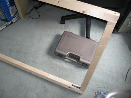
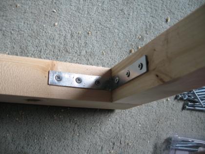
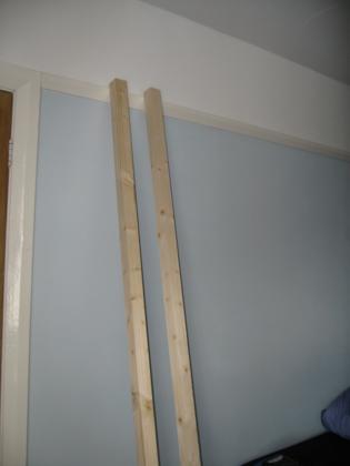
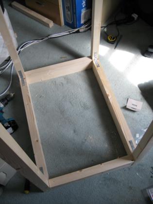
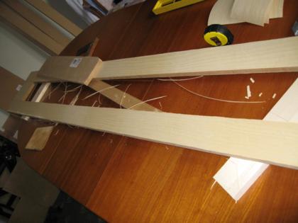
Phase 1 – Building the frame
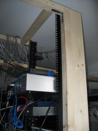
The frame was constructed using 5 44x44x2400mm PSE timbers and 1 44x94x2400mm PSE timber to give strength at the base. Some small modifications had to be made to get the front rails installed (had to move one of the top cross-beams back).
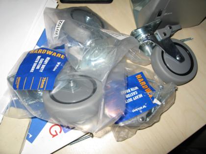
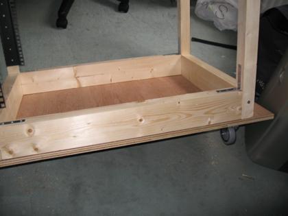
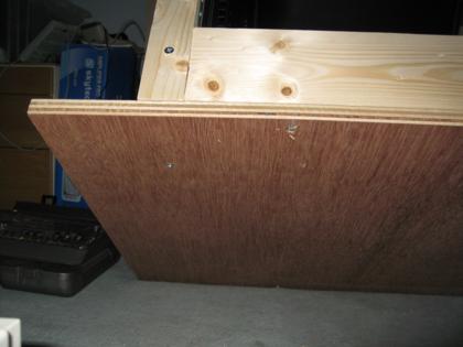
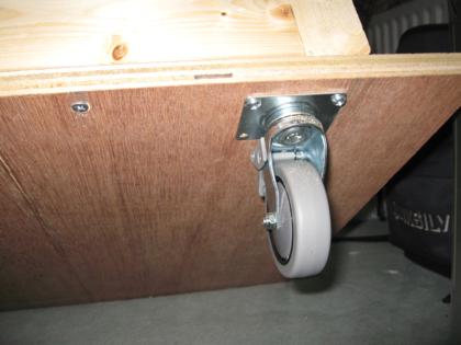
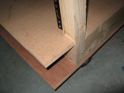
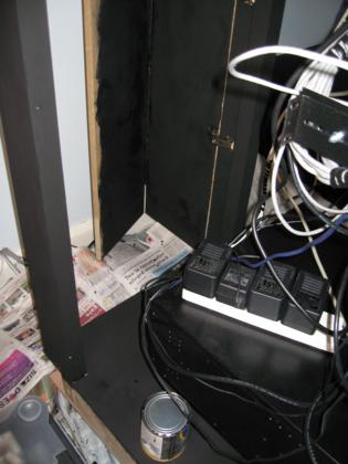
Phase 2 – Making it portable
A base was added to make the frame portable and give something for non-mounted items (like the 2.2KVA UPS) something to sit on. The base consists of a plywood lower part with castors and an MDF upper part.
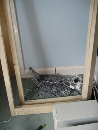
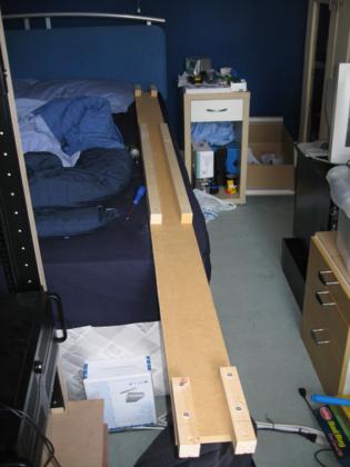
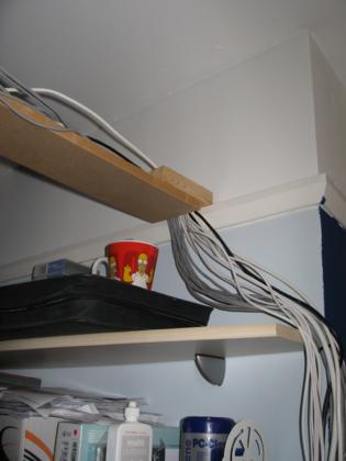
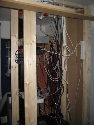
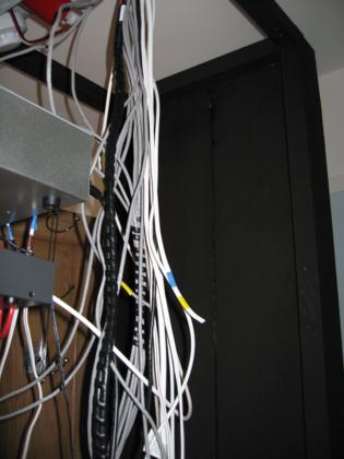
Phase 3 – The cable tray
One of the other projects underway is wiring the house up with Cat5 and speaker cable, and there are several other cables that need to cross the room to get to the cabinet. Initial thoughts were to lay the cables under the floor but this was going to be too much work. The cable tray was built from an MDF off-cut and some left-over battons from another cupboard. It’s not the best looking thing, so it might get painted or replaced with guttering.
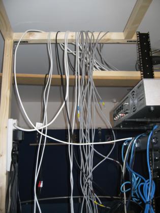
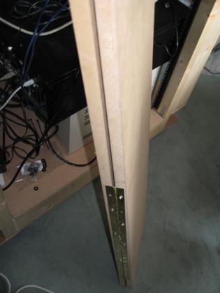
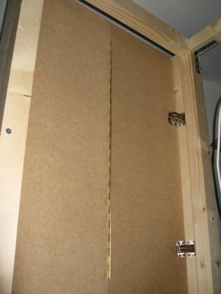
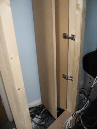
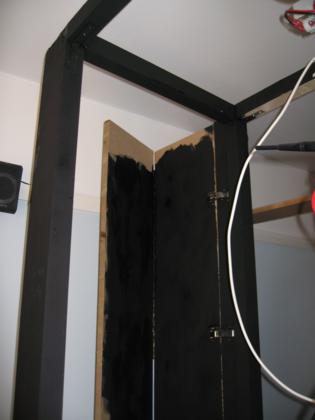
Phase 4 – Adding the rear doors
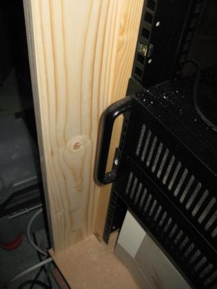
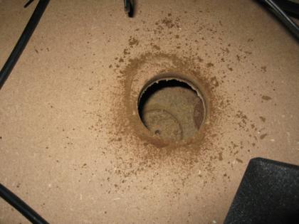
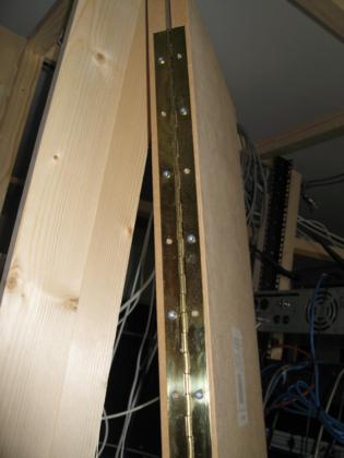
The doors are mounted on some thinner PSE beams which are attached to the uprights on the frame. This provides sufficient distance between the rack rails and the doors to allow for protruding handles and cables from the equipment. The doors were made from 18mm MDF (the same as my wardrobe doors), and hinged using piano hinge in the middle to allow it to fold. This gives access from one side while reducing the amount of space required behind the rack. The doors were attached to the frame using cupboard hinges (no cut-out required). At this point a hole was drilled in the base to allow cable access while the doors are closed – be careful not to get the drill stuck in the whole like I did, forcing me to take part of the frame apart to be able to lift the base and release the hole saw.

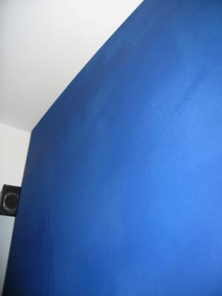
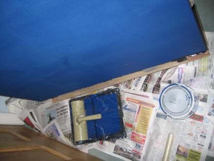
Phase 5 – Painting
Matt black blackboard paint was used for the frame, base and rear doors. 2 coats was enough to give a good finish.
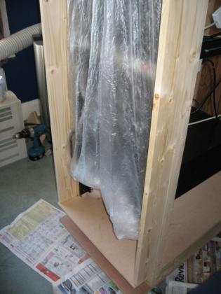
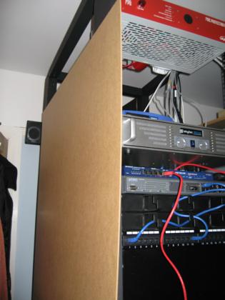
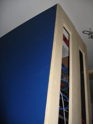
Phase 6 – Adding the side panels
3mm MDF was used for the side panels. Originally it was intended that the panels be much thicker and stronger to allow direct mounting of equipment (e.g. an LCD or Plasma display) to the sides, but this would have added significant weight to what was already quite a heavy structure.

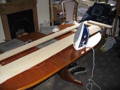
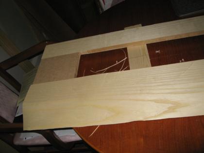
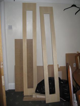
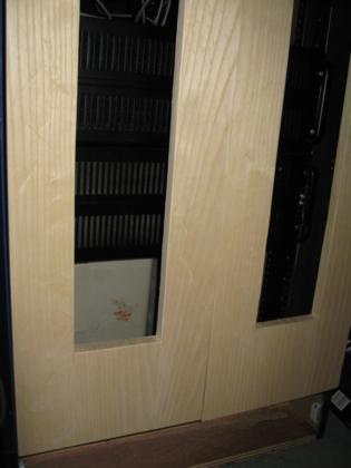
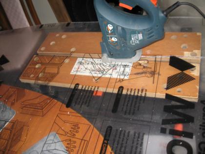
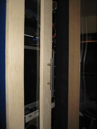
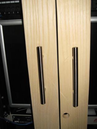
Phase 7 – Adding the front doors
The front doors were constructed from 18mm MDF and veneered with ash. Acrylic glass sheets allow direct viewing of the equipment within, whilst keeping the noise contained and the hardware secure.


Phase 8 – Adding the top and improving ventilation
This is the next phase, cutting a hole for cool air at the bottom and adding the top with 120mm fans.
More Images
The full gallery of photos from this project is available.
Very cool, makes me wish I had the space for doing projects like this. Not sure my house mates would appreciate the electricity bill though!
Do you have any projects not like this underway? I’m trying to come up with ways to reduce the electricity consumption. At the moment the drives in boron (the main fileserver for the house) are set to spin-down after 10 mins. I think what is also needed is some sort of low-power solid-state bittorrent client, so that I don’t have to leave a relatively hungry machine on to do simple downloads.
I would like to see a solid state bit torent client as well.
Have you noticed a huge increase in your electirc usage sence adding the home automation system?
In order to save power, I think I am going to use some NAS for the bulk of my storage needs, and keep everything else relativly small. Just and idea at this point.
I have found that some NAS boxes are starting to include bittorrent clients. I’m thinking of writing one to suit my needs, so that I can leave the backend running on the fileserver, but have the full interactivity of a GUI client running on the machines that I actually use. Best of both worlds! I then won’t need to have my desktop computer on to download torrents easily – could even add them remotely.
The electricity bills have increased, but they should start to go down as I make more efficient use of the systems.
I have an older NAS box, but I’ve been very disappointed with its performance – max 5MB/sec speed and it crashes at a low level in the network stack, taking the entire of my network with it sometimes. I went for a cheap one though, which is probably where the problem lies. More expensive ones from well-known brands should be a lot more reliable.
Hi,
Nice built. Absolutely loving it. Hey do you have detailed dimensions by any chance? I am planning to do one as well, but just 10u so that it fits under my desk. And oh is it definitely strong enough to hold a good UPS?
As for NAS, beware. I’ve seen some NAS boxes drawing upwards of 75w. I would recommend building a PC-based NAS instead, with something like a VIA EPIA motherboard, with either FreeNAS or unRAID as the OS. Especially unRAID, it has good spin up/down management. Should only consume 30w or so at max with two 3.5″ hard drives. And of course in a rack mount case 😀
Thanks.
I’ve got the original sketches on my desk. I’ll scan them in and post them shortly. They include the dimensions and a list of the timber I used (or planned on using).
Building a low-power NAS box sounds like a good idea. I’ll look into it – thanks for the tip! At the moment my storage needs are met by my self-built Ubuntu machine, boron. It’s got 1.7TB installed, but it’s based on a standard P4/ATX combination so draws a fair bit more than an EPIA would.
Hi,
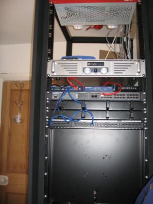
I notice you have a fire protection unit fitted at the top of your rack, (nice job by the way), can you tell me where you got it from and what was the cost? I have a small similar setup where some of the kit is on unattended 24/7 and I would like to feel a bit happier if something did go wrong there would be some form of protection.
Thanks & Regards.
I found the FPU on eBay, and it cost something like £20 including postage. The company who produced it went bust a while ago though, so I’ve not been able to find any documentation.
At the moment it’s not plugged in cos when it has power the alarm goes off, presumably as a self-test. I need to take it out the rack, dampen the sounder and figure out how to get the thing to work properly.
I think these things are quite rare, since they are only really available 2nd hand and are a fairly unique product so I don’t know if you’ll be able to find one on eBay too.
Thanks for that info. I have had a look on e-bay but nothing available at the moment. I have however come up with this site: http://www.apwstuff.co.uk/apw_accessories.htm
which seems to describe the unit you have to a tee, could you possibly confirm?
Regards,
Yep, that’s the one. That’s the only remotely useful information I’ve been able to find so far. There are a few PDF brochures around too, but they dont really carry much by way of useful info.
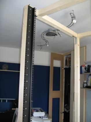
Where did you buy the rack rails from, I have been searching the internet and can only find people that sell the cabinets themselves?
Andy.
I got them from Maplin, the only place I could find proper rails.
http://www.maplin.co.uk/module.aspx?ModuleNo=1784&doy=9m3
i recently ordered a compaq 22u rack (too lazy and two left handed to build one myself) which will be delivered in just over a week.
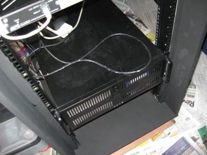
in your photos i noticed you also have a codegen 4u-500 (or 4u-600) pc case.
i was wondering if you were able to hang your cases in your rack by only screwing on at the front? you have no supports? if so, it would save me mucho dinero not having to buy rails or planks…
The cases pictured are actually the Compucase S411, although some companies do rebrand them I think so they could also be Codegen.
The ones I have can be fixed just to the front rack rails with all 4 screws without any rails. If there’s nothing below though you’ll need some muscle to hold the case in place while you screw it in.
The bottom case now has rails so that I can easily move it in and out for maintenance, but the top one is still just mounted at the front without any problems.
Beware that the vertical rack strips will need to be quite strong to allow the case to be supported by just the front panel, but being a reliable make the Compaq one you’ve ordered should do the job nicely. Will you be putting photos up of your setup for the rest of us to see?
great! thanks for the info.
the cases seem to be the same: i’ve had a look at your gallery in the mean time. i already had one and two more are on there way (in the post).
i might get some rails in the future, but the rack, extra cases etc have been stretching my budget, and maintenance should be minimal with decent equipment.
you want photos? your wish is my command. i’ll add an url when my rack is delivered…
quick ‘n dirty:
http://bsd.bluuurgh.com/rack/index.php
arrived this afternoon. we need a bigger house…
Cool. Cases mounted fine I see. They look good.
I liked your design so much (lovely job!), I’ve started to build my own 22u version. And you’re right about the cost, though, the trip to Homebase cost me over 130 quid! (not counting the side rails from Maplins) It’ll be worth it just for the reduced noise level. One question; Where did you get that iron-on wood grain effect sheet from? I was unable to source it at any of our local DIY places. Cheers.
Great to see that this project has inspired someone else! I got the iron-on wood laminate (it’s real wood) from eBay: http://stores.ebay.co.uk/Vale-Veneers
Hope you’ll write up about your build, and take some photos along the way.
I have found this company if anyone is interested in Rack Mount Fire protection Dolutions. Forget the FPU this one is current and seems much better. http://www.redetec.co.uk
I hope they stay in business long enough for me to do my next project requiring rack-level fire protection (and when I can afford to buy one new, rather than expired second hand). Every other business making those sort of things seems to go bust. My FPU is currenty unplugged until I can figure out the safest way to use it given that the alarm is disabled.
I was wondering that if you could e-mail your blueprints to me, because want to build my own 19″ rack
Would you consider sharing your blue prints? I need to build one. Thanks.
Hi, love the build, iam in the porcess of designing my build to go under my stairs at home, not quite as tall prob onoly 37U-40U depending on the base i have to use, did you only want a caster base so you could move your unit, i really want to nake mine a pull out systm but am strugling to find runners to support a big and heavy unit unless i want to pay £400 or so which i dont, just for runners, if you have any ideas i would love to know. if i have to use casters my unit would have to reduce in size by upto poss more than 2U which would be too small. ill be trying to find somewhere to post my build when i start it.
Hi Kevin. Have you considered making your own runners out of some steel ‘track’ and ball bearings to take the weight? This is how rack rails tend to operate, and they can handle significant loads (though not an entire rack!).
I’m doing racks for business at the moment, nothing built yet, but some ideas, and I’m not the best blueprinter in the world lol. I’ve got some ideas as far as cabinets with wood panels for siding, and LCD VESA mounted screens on the side, with a small keyboard mouse tray, things of that nature. I just need help blueprinting it for a more professional look, to give to my supervisor, rather than spending X amount of $ on a new cabinet. Any suggestions as far as free software I can use to draw them up?
Google Sketchup is quite good for producing design mock-ups to show to your boss. I’ve used it to design my next rack cabinet, although it may not be me building it this time.
Any chance of seeing your plans (dimensions etc)
Any chance of you sending your blueprints and complete build list ?
Been wanting to do this for some time.
As the current server set up is not girlfriend approved, it’s time to get busy.
Very nice 🙂