Measuring power consumption

A recent electricity bill has prompted me to investigate how much power is being used by each device in and around the cabinet in the hope of figuring out what can be replaced to reduce running costs. I’ve had a power monitor from Maplin for a while, but most of the time it’s been monitoring total power consumption of the rack.

Power

  • UPS: ~50W non-charging

Networking

  • 24 port 10/100 switch: 25W
  • 4 port 10/100/1000 switch: 18W
  • 5 port 10/100/1000 switch: 8W
  • Router: 3W
  • Modem: 3W

Computers

  • Boron (fileserver): 150-190W
  • Aluminium (desktop): 250-295W
  • Barium (HTPC): 66-85W

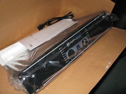
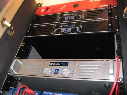
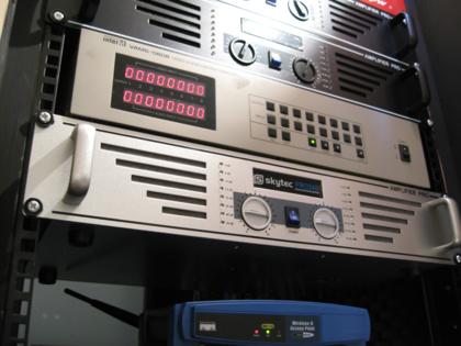
The audio system components haven’t been measured yet because at the moment they aren’t ready to drive a load and measuring the idle consumption wouldn’t be very meaningful. The amplifiers will be switched off when not in use and won’t be used that much compared to the items listed above.

Based on the data above, I have replaced the 3 switches with 1 switch. I have been investigating replacing boron with a collection of NAS devices for storage and a low-power ITX-based machine for services such as DHCP and DNS. However this is currently quite an expensive option.

Aluminium is a gaming-spec PC so will always consume quite a bit of power, however I’ve got some software under development which should mean that I won’t need to keep it on to download the occaisional torrent – that job could be offloaded to boron or my hosted server.

Barium is only on when I want to watch a DVD, a video or recorded TV from MythTV. It was specced to be quiet and consume as little power as possible with a Core 2 Duo CPU, 1GB DDR2, a passively cooled HDCP-capable VGA/DVI graphics card and a quiet PSU.

I’m going to continue to look at reducing consumption not just in the rack but around the rest of the house.

Serial port problem solved

Thanks to the chip manufacturer of the cheap serial port card, I’ve managed to get some extra serial ports working. If you can’t figure out how to get additional serial ports working, I recommend this guide [ZIP, 792KB] available from the Moschip driver download page. It should be valid for most models of serial cards, and explains how to add more than the standard 4 ports that most linux installs have.

Now that this problem is out of the way I can continue with writing the remote control software for the audio system.

Serial port problem part-way resolved

Having put the 4 port serial card back into boron, the onboard port now works again, so I’ll probably continue with developing the software. The expansion card still doesn’t work though, so I’ve ordered a cheap 2-port card from eBay in the hope that a different card will work.

Before reinstalling the card I upgraded Ubuntu to see if that would help (it didn’t) which brought its own scary moment of the 1TB RAID volume being dead. That too is solved now – the drive letter assignments had changed.

Hitch with the audio system

Today I started development of the software to control the whole-house audio system. It’s written in C# and based on the MiniHttpd project – a small but powerful implementation of a web server in C#.

However, when it came to testing the first bits of code, I’ve envountered a problem. A while ago I bought a 4 port RS232 serial card to go into boron, because the motherboard only has 1 onboard port which isn’t enough for the UPS, the matrix switcher and probably some other things such as connections to network switches.

The new card shows up fine in lspci, seems to be ok when running setserial -gb, but when trying to send or receive data nothing happens. Thinking it might be a conflict with the onboard port, I went into the BIOS and disabled it. Still nothing. So I swapped the card into another machine and re-enabled the onboard port in boron‘s BIOS. Now the onboard port doesn’t work either.

I’m going to contact the manufacturer of the card for some help. But for the onboard port I’m completely stumped. It too shows up in lspci and setserial -gb (though only when running using sudo, which wasn’t necessary before) but any attempts to use the port result in various I/O error messages. I was worried that the new card may have killed the serial communication capabilities of the matrix switcher and the UPS, but I’ve confirmed that at least the matrix switcher still works by connecting it to my test machine, iron.

If anyone thinks they might know what’s getting on, please get in contact via the comments for this post – I would be very greatful for any help.

Successful test of audio over CAT5

I have just successfuly tested transmission of near-line-level audio over the cat5 cables I’ve recently finished installing.

DAB Radio

The amplifiers and matrix switcher have been installed for a while, but until now I’ve not performed any tests of sending audio from one part of the house to the matrix switcher, through the appropriate amplifier and out of the installed speakers.

Green 2m CAT5 cable

I bought some 2m green cat5 cables off of ebay, but rather than use them as normally intended I cut one of them into two equal lengths.

After removing a length of the outer insulation at the cut ends, I attached 2 phono plugs to one length and a stereo 3.5mm jack to the other (with a little help from wikipedia for the correct pinout of the latter).

A multimeter was used to verify that there weren’t any shorts – wire-wrapping the connections was a little fiddly – before I plugged the cables in for testing.

Jack connected to DAB radio

The length with the phono plugs was connected to the matrix switcher and the RJ45 patch panel, and the other length was attached to the headphone output of a DAB radio in the kitchen and one of the 2 ports in that room.

Patch panel connection

The successful test is promising for the completion of this project. I have ordered and bid on 2 more sets of speakers for the dining room and kitchen, and the final amplifier will be ordered soon.

The software needs to be written to control the system, but I could probably do most of that in a weekend. A little more hardware in the form of a touchscreen capable low-power computer and an iPod Touch will be required to run the web-based front-end for the software. Then the system should be complete.

Look out for a video demo of the system once I’m happy with it!

Completing the data wiring

img_2141.JPG

Today I added the final 4 network points – there are now a total of 24 around the house.

The wiring project started about 14 months ago, with the plan to have at least 2 network points in all rooms except the bathroom. The final distribution has ended up as:

  • Living room: 6
  • Dining room: 4
  • Kitchen: 2
  • Pantry: 4
  • Landing: 2
  • Bedroom 1: 4
  • Bedroom 3: 2

img_2130.JPG

Despite considering that 24 ports might be a little excessive, I’ve come to realise that 24 ports isn’t quite enough especially when it comes to distributing analogue audio & video over CAT5 (i.e. not as IP data) since at least one port is required for each A/V combination depending on the quality of the signal desired. The living room should probably have 4 more ports, the kitchen could do with at least 2 more and a couple by the front door would come in useful for security purposes.

img_2037.JPG

I’ve learnt a lot from the experience of doing this wiring, such as how to lift floorboards, that lathe & plaster ceilings are extremely fragile and plastering is nowhere near as easy as it looks.

img_2076.JPG

Running the cables before moving in was certainly a good idea. It would have taken me probably another 12 months otherwise to get to this stage. It’s taken a lot more work than I expected, although the overall time is down to being in a lazy, bored and/or apathetic mood most weekends. I’m glad I did it though – the ports have come in useful for the MythTV system, for the family computer and soon enough the whole-house audio system. I’m also using them to trial some IP video cameras.

img_2071.JPG

img_2134.JPG

New amplifiers

img_1685.JPG

Last month, as per my schedule of purchases, I bought 2 more amplifiers. These will serve zones 2 (dining room) and 4 (master bedroom). I ordered them from the same place as the first, despite having a rather unpleasant experience with the trader on eBay thanks to their appauling checkout/payment system and problems with their UK bank account (they are based in Germany).

img_1687.JPG

The first amplifier, for zone 1 (living room), is silver. I was a bit surprised to find that the 2 that I received were in black. I was hoping to get my rack looking tidy by keeping the same look throughout the cabinet. Black goes better with this scheme, but the silver one stands out now. To balance it out I’m hoping to get a silver one next. A note of appology was included with the amps, which includes a 5 euro discount on the next order. I probably won’t be getting the next amp for a while, to keep my budget under control having spent quite a bit on the matrix switcher.

img_1691.JPG

The VAMS-0808 matrix switcher and determining its protocol – part 2

img_1738.JPG

As I mentioned last month, I bid on and won an 8×8 AV matrix switcher on eBay. The switcher arrived the Monday following the Saturday that I won it (speediest delivery ever!), so I took it home and plugged it all in.

I rummaged around for a serial cable to connect the switcher to boron, the Ubuntu file server and found something that I thought would do the job. Sadly the switcher has a male connector, whereas for a standard serial cable it should be a male connection on each end. So, slightly disappointed, I went ahead and ordered a M-F serial extension from eBay, assuming that this would do the job. This attempt also failed – the matrix switcher would not respond to any of the commands that I thought it should, and nothing was being returned either. After a bit more research in the little documentation that I had I noticed that the switcher requires a cross-over cable AKA a null modem cable.

The next cable I ordered was a M-M cable, so I got an M-F converter at the same time. Success! I now have the ability to control the matrix switcher via the RS232 on boron.

img_1733.JPG

The following weekend I set about writing a prototype of the software to communicate with the switcher. The switcher operates in such a way that state is important, since switching channels requires at least 2 commands and at any time someone can press a button on the front panel to issue any command.

When a button is pressed on the front, a message is sent via the serial port to indicate the action that has taken place. Similarly, when an instruction is sent to the unit over the serial connection a reply is received indicating whether that command succeeded or not. Sometimes the switcher doesn’t notice that it’s been sent an instruction, so to get around that I ended up sending the same message up to 3 times.

The resulting prototype works quite well. I may release the source code at some point.

Here’s a video demonstrating the software and the switcher:

[youtube:http://www.youtube.com/watch?v=rG0N6q7gqVg]

The VAMS-0808 matrix switcher and determining its protocol

A significant part of the whole-house audio system is the matrix switch that allows any audio input to be listened to on any audio output. I’ve been looking for a suitable switch for several months now (by suitable I mean cheap enough, but still capable). My requirements are that it has 8 inputs, 4 outputs and RS232 support.

Once again, eBay has proven it’s worth and I’ve found something for a lot cheaper than my previous find. It has 8 inputs, 8 outputs, RS232 support and includes composite video switching too. S-video switching would have been nice, but that feature seems to double the price so I’m happy to go with the compromise of composite video.

Of course there’s always a hitch with these low-cost items made in the far-east, and it’s almost always that the websites are absolutely rubbish – crafted to work only in IE, badly structured, lacking any useful technical information and generally broken. Thankfully, Google has come to the rescue and I’ve managed to find the software that controls the VAMS-0808 (IE is required, and the installer doesn’t even open in Vista – works OK in XP though).

I’ve got a Virtual PC with XP installed, just to connect to work’s VPN which until recently didn’t have a Vista client. One of the handy features in Virtual PC is the ability to map COM ports to physical ports, named pipes or a text file. I set COM2 to redirect to a text file, and voila, I now know how the software talks to the switcher.

Communication protocol for the VAMS-0808 (not tested yet)

This is what I’ve figured out so far:

All commands start with a 0 (zero), and are committed with a Windows new-line (\r\n). Some actions require multiple commands in order, for example channel switching. An output channel selection command must precede an input channel selection command.

  • 0CO1 – 0CO8: Select output channel 1-8
  • 0ALL: Select all output channels
  • 0CI1 – 0CI8: Set input channel 1-8 for currently selected output channel
  • 0OFF: Disconnect currently selected output channel (input channel 0)
  • 0VCS: Subsequent commands switch only video
  • 0ACS: Subsequent commands switch only audio
  • 0AVS: Subsequent commands switch both audio and video
  • 0LOO: Disable hardware lock
  • 0LOI: Enable hardware lock

I have no idea if the switch actually returns any status codes since I haven’t got it yet, but hopefully it’ll be on it’s way to me soon!

Edit: 0OFF actually means disconnect the selected channel, not disconnect all channels. Also: woo! It’s arrived! Very speedy delivery indeed.